The purpose of this article is to provide you with a clear step-by-step process on how to add various CAD objects to your floor plan in the DotActiv software. We also explain how to copy CAD objects to a new floor plan.
You have the opportunity to add a variety of different CAD objects to your floor plan in the DotActiv software. These include Walls, Lines, Gondolas, Aisle Indicators, and Tellers.
Adding Walls
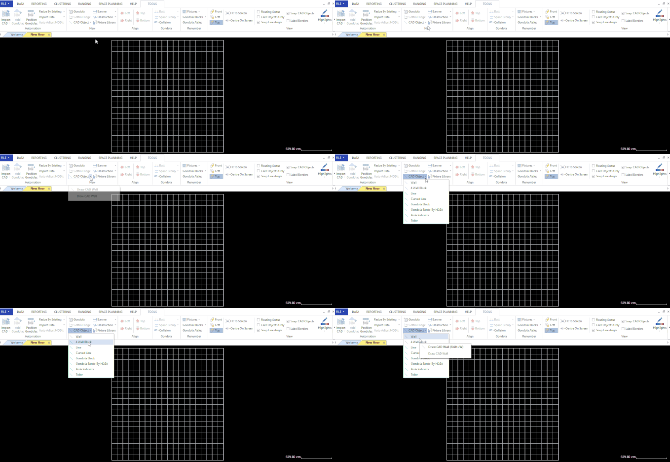
After opening your floor plan, ensure that you are in the ‘Tools’ tab. Next, select the drop-down arrow beside ‘CAD Object’ in the ‘New’ section. From the drop-down menu, select’ Wall’.

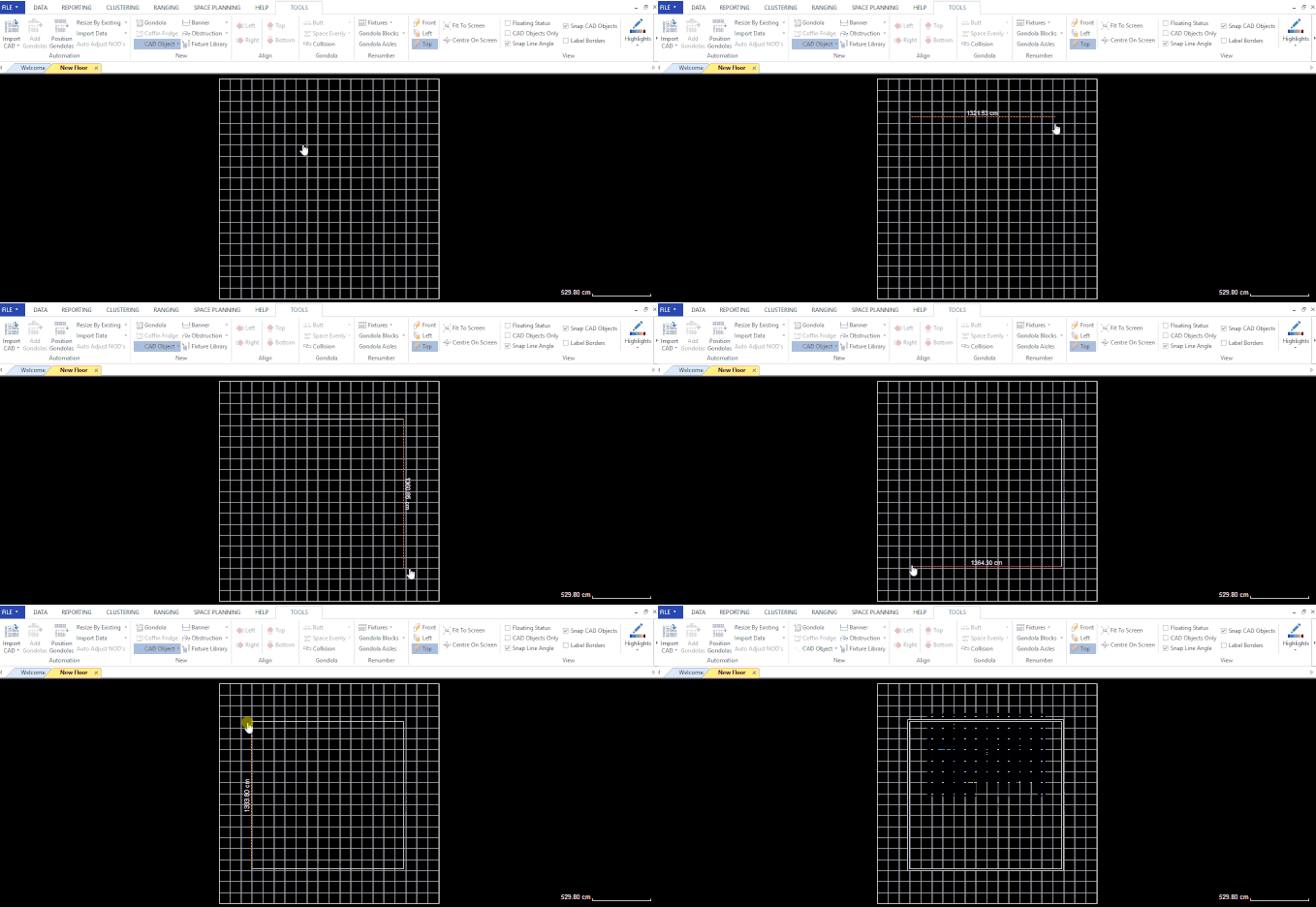
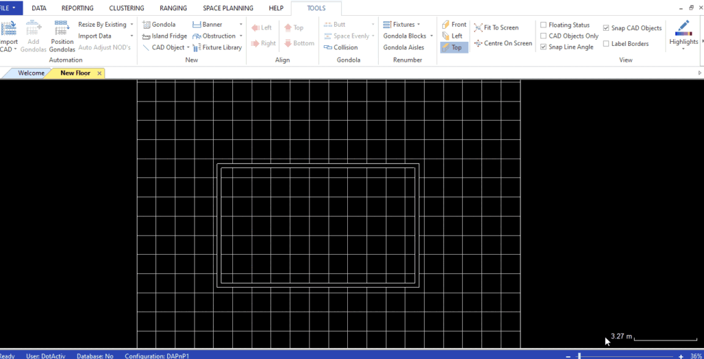
Click on the area where you would like to draw the wall and then click at each point to position the wall around the floorplan and left-click to end drawing the wall. Right-click to release.
A dialog box will pop up asking if you like to connect the last line to the closest. Click ‘Yes’.

Adding Lines
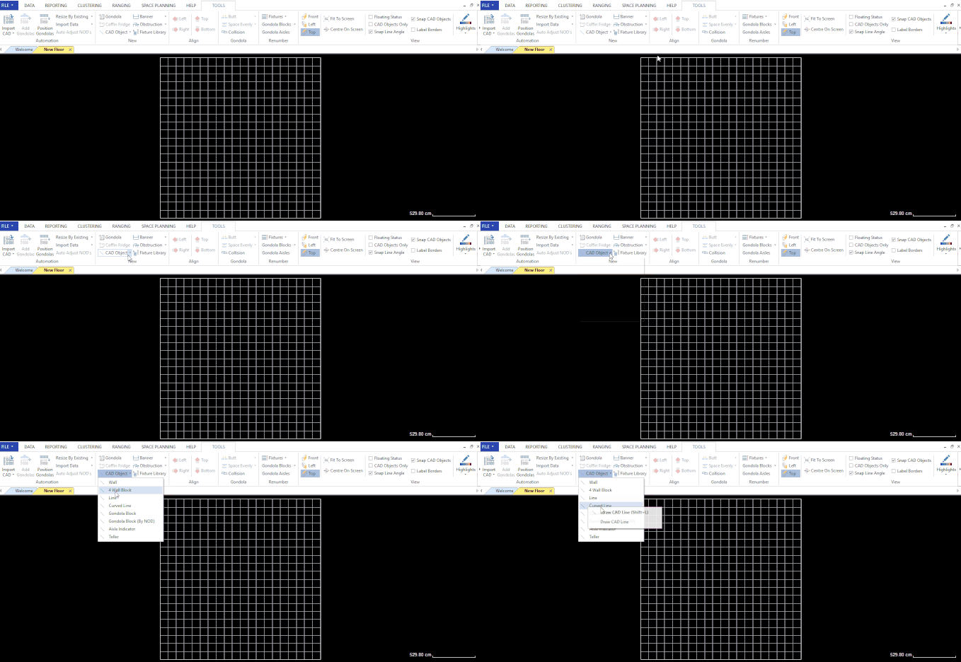
After opening your floor plan, ensure that you are in the ‘Tools’ tab. Next, select the drop-down arrow beside ‘CAD Object’ in the ‘New’ section. From the drop-down menu, select ‘Line’.

Click on the area where you would like to draw the line. Pull the line until it is the desired length. Left-click to end drawing the line. Right-click to release.

Adding Gondolas
After opening your floor plan, ensure that you are in the ‘Tools’ tab. Next, select the drop-down arrow beside ‘CAD Object’ in the ‘New’ section. From the drop-down menu, select ‘Gondola Block (By NOD)’.
Please note that there can be no duplicate groupings when adding gondolas to a floor plan.

Click on the area where you would like to draw the gondola block. Pull the gondola block until it is the desired length. Left-click to end drawing the gondola. Right-click to release.

To create the other side of the gondola, right-click on the gondola. Then, from the context menu that pops up, click ‘Create Mirror Copy’.

Next, select both sides of the gondola. Right-click and select ‘Add Ends’ from the context menu as seen in the GIF below.

You will notice that there are two options when selecting the dropdown to draw a gondola block.
The first option is ‘Gondola Block’ and the second option is ‘Gondola Block (By NOD)’. There is no major difference between these two options except that the first option allows you to create a gondola block using measurement in cm and the second option allows you to create a gondola block using drop count.
Please note that option one will create a gondola block by the length you require in cm and option two will create it by the number of drops in a run.
Gondola blocks can be used for functions such as snake aisles, gondola ends, grouping categories together, and to allow planograms to snap into position and be packed next to each other. You can read more about the benefits and purpose of Gondola Blocks in this article.
Adding Aisle Indicators
After opening your floor plan, ensure that you are in the ‘Tools’ tab. Next, select the drop-down arrow beside ‘CAD Object’ in the ‘New’ section. From the drop-down menu, select ‘Aisle Indicator’.

Click on the area where you would like to draw the aisle indicator. Pull the aisle indicator to the desired length. Left-click to end drawing the aisle indicator.

Adding Tellers
After opening your floor plan, ensure that you are in the ‘Tools’ tab. Next, select the drop-down arrow beside ‘CAD Object’ in the ‘New’ section. From the drop-down menu, select ‘Teller’.
Click on the area where you would like to draw the teller. Pull the teller to the desired length. Left-click to end drawing the teller. Click and drag to the desired position.

To change the dimensions of the teller, double-click on it to open the ‘Teller Properties’ window. Then click ‘OK’.

Adding Doors
Once you have created your wall, right-click on it and select ‘Insert Object’ from the context menu that pops up.
In the ‘Insert Object’ window, you can select the type of door you require and adjust the position and width where required. You can select a ‘Single’, ‘Double’, ‘Stacked’ or ‘Double Stacked’. You can also add a window to your floor plan if it’s required.

Adjusting the width changes the size of the inserted door. Once happy, click ‘OK’ to insert the door.
Copying CAD Objects
If you would like to copy any selected CAD objects onto a New Floor Plan, you can follow the steps below.
This can be accessed once a CAD object has been added to your floor, followed by selecting ‘Copy to New Floor’ from the right-click menu. As seen in the gif below, the software automatically creates a new floorplan with the desired CAD object.
Adding a new CAD object in the DotActiv Software is simple and easy. Should the above steps not work for you, please create a support ticket and the DotActiv support team will assist you in uncovering the issue.
